This time we bring you a way to connect a gamepad (a Nintendo Wii Classic Controller) to a PC using a STM32 and a USB connection. First, the idea was to add a gamepad controller to the Space Invaders project but after interfacing the gamepad the idea became less challenging. So we decided to go further and add USB support to the project.
This way we managed to convert the AK-STM32-LKIT board into a gamepad-to-USB interface. The result is a Nintendo Wii Classic Controller fully compatible to play any game on the PC.
Hardware
What you need to complete the project is:
- a STM32F10x board. We use the AK-STM32-LKIT (36-pin, QFN STM32F103T8),
- a Nintendo Wii Classic Controller,
- some soldering skills.
As with the previous projects, this one will not need any external components.
The first thing to do is to cut the gamepad connector wire (if you don’t want to cut the cable you may buy a cheap extension cable). You will notice that there are 4 cables plus shielding:
| Color |
Function |
AK-STM32-LKIT pin |
| Red |
+3.3V |
+3.3V |
| White |
GND |
GND |
| Yellow |
I2C SCL |
PB6 |
| Green |
I2C SDA |
PB7 |
The gamepad talks in I2C protocol, hence the yellow and green cables are for communication; the red and white are for power supply.
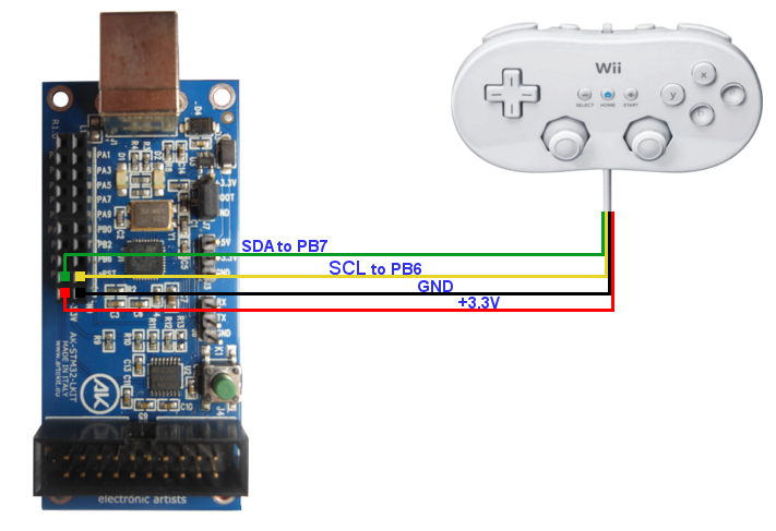
In the above graphic, the white cable (GND) from the controller is represented by the black line.
Software
The project uses the STmicroelectronics USB library for STM32. This library allows you to use, in some relatively easy way, the USB capabilities of the STM32 line, including USB client (the one we use for this project), USB host and USB On-The-Go, were available. The library comes with examples for some types of USB devices. One of these is an example for a HID mouse/joystick, that we used as the base for this project.
The library is split in two parts: a generic core, and a modificable user part that can be adjusted to fit the desired USB device. So we took the user part and hacked it to remove references to other devices (like the Connectivity Line devices) to make the code cleaner. The source code is for the KEIL uVision environment (you may find a download link at the bottom of the page).
Reading from the gamepad
The controller communicates in I2C at 400KHz (fast mode). There is an initialization step that configures the encryption of the data to be transmitted. For this example the encryption is disabled.
Thanks to WiiBrew for the information about the controller protocol. More details on the WiiBrew page dedicated to the Wii Classic Controller. Here is the part from said page describing how the data is trasmitted from the controller:
|
Bit |
| Byte |
7 |
6 |
5 |
4 |
3 |
2 |
1 |
0 |
| 0 |
RX<4:3> |
LX<5:0> |
| 1 |
RX<2:1> |
LY<5:0> |
| 2 |
RX<0> |
LT<4:3> |
RY<4:0> |
| 3 |
LT<2:0> |
RT<4:0> |
| 4 |
BDR |
BDD |
BLT |
B– |
BH |
B+ |
BRT |
1 |
| 5 |
BZL |
BB |
BY |
BA |
BX |
BZR |
BDL |
BDU |
LX,LY are the left Analog Stick X and Y (0-63), RX and RY are the right Analog Stick X and Y (0-31), and LT and RT are the Left and Right Triggers (0-31). The left Analog Stick has twice the precision of the other analog values. BD{L,R,U,D} are the D-Pad direction buttons. B{ZR,ZL,A,B,X,Y,+,H,-} are the discrete buttons. B{LT,RT} are the digital button click of LT and RT. All buttons are 0 when pressed. Nintendo games calibrate the center position of the Analog Sticks upon power-up or insertion of the Classic Controller.
USB
Our STM32 will be seen at the PC as an USB HID (Human Device Interface) device. This means that we will need an USB HID Report descriptor implemented in our software. Long story short: an USB HID device will “teach” the host (the PC) how the device is composed (quantity of buttons, purpose, etc.) and how the data will be transmitted. This is done by implementing an USB HID Report descriptor.
Making a Report descriptor directly by coding it can be hard. But there is a program called HID Descriptor Tool that allows you to create the Report descriptor (by clicking and adding elements to a list) and then export it as a C array. You can open the included gamepad.hid file to see how it was generated.
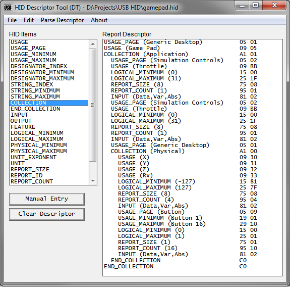
This is the result for the Report descriptor that we’ll be using:
const u8 wiiccReportDescriptor[74] =
{
 0x05, 0x01, // USAGE_PAGE (Generic Desktop)
 0x09, 0x05, // USAGE (Game Pad)
 0xa1, 0x01, // COLLECTION (Application)
 0x05, 0x02, // USAGE_PAGE (Simulation Controls)
 0x09, 0xbb, // USAGE (Throttle)
 0x15, 0x00, // LOGICAL_MINIMUM (0)
 0x25, 0x1f, // LOGICAL_MAXIMUM (31)
 0x75, 0x08, // REPORT_SIZE (8)
 0x95, 0x01, // REPORT_COUNT (1)
 0x81, 0x02, // INPUT (Data,Var,Abs)
 0x05, 0x02, // USAGE_PAGE (Simulation Controls)
 0x09, 0xbb, // USAGE (Throttle)
 0x15, 0x00, // LOGICAL_MINIMUM (0)
 0x25, 0x1f, // LOGICAL_MAXIMUM (31)
 0x75, 0x08, // REPORT_SIZE (8)
 0x95, 0x01, // REPORT_COUNT (1)
 0x81, 0x02, // INPUT (Data,Var,Abs)
 0x05, 0x01, // USAGE_PAGE (Generic Desktop)
 0xa1, 0x00, // COLLECTION (Physical)
 0x09, 0x30, // USAGE (X)
 0x09, 0x31, // USAGE (Y)
 0x09, 0x32, // USAGE (Z)
 0x09, 0x33, // USAGE (Rx)
 0x15, 0x81, // LOGICAL_MINIMUM (-127)
 0x25, 0x7f, // LOGICAL_MAXIMUM (127)
 0x75, 0x08, // REPORT_SIZE (8)
 0x95, 0x04, // REPORT_COUNT (4)
 0x81, 0x02, // INPUT (Data,Var,Abs)
 0x05, 0x09, // USAGE_PAGE (Button)
 0x19, 0x01, // USAGE_MINIMUM (Button 1)
 0x29, 0x10, // USAGE_MAXIMUM (Button 16)
 0x15, 0x00, // LOGICAL_MINIMUM (0)
 0x25, 0x01, // LOGICAL_MAXIMUM (1)
 0x75, 0x01, // REPORT_SIZE (1)
 0x95, 0x10, // REPORT_COUNT (16)
 0x81, 0x02, // INPUT (Data,Var,Abs)
 0xc0, // END_COLLECTION
 0xc0 // END_COLLECTION
};
This Report descriptor indicates that:
- our device is a gamepad, with 2 throttles, 2 analog sticks, and 16 buttons.
- the throttles will produce a value between 0 (released) and 31 (full pressed) and that each value will be sent in 8 bits.
- the analog joysticks will produce a value between -127 and 127 for each axis, and each value will be transmitted in 8 bits (32 bits total for four axis).
- the buttons will be sent as 16 bit, using a bit per button (0 for released, 1 for pressed).
The gamepad does not have 16 buttons, but 15. We have set 16 because the data declared in the Report descriptor must be byte-aligned.
Now what the example program does is to retrieve the data from the gamepad (using I2C) and convert the values to fit the following structure (WII_CC_DATA). This structure will hold the information about the current state of the gamepad.
typedef struct wiiCCButtonsTag
{
 u8 dummy:1;
 u8 rtrigger_push:1;
 u8 plus:1;
 u8 home:1;
 u8 minus:1;
 u8 ltrigger_push:1;
 u8 down:1;
 u8 right:1;

 u8 up:1;
 u8 left:1;
 u8 zr:1;
 u8 x:1;
 u8 a:1;
 u8 y:1;
 u8 b:1;
 u8 zl:1;

} WII_CC_BUTTONS;

/* WII Classic Controller Data */
typedef struct wiiCCDataTag
{
 s8 left_analog_x;
 s8 left_analog_y;

 s8 right_analog_x;
 s8 right_analog_y;

 s8 left_trigger;
 s8 right_trigger;

 WII_CC_BUTTONS buttons;

} WII_CC_DATA;

/* We send the data using the exact same order
 * declared in the Report descriptor. Here is an example.
 */
u8 packet[8];
WII_CC_DATA data;

/* Read from gamepad */
wiiCCRead(&data);

/* Order the data to be sent */
packet[0] = (u8) data->left_trigger;
packet[1] = (u8) data->right_trigger;
packet[2] = (u8) data->left_analog_x;
packet[3] = (u8) data->left_analog_y;
packet[4] = (u8) data->right_analog_x;
packet[5] = (u8) data->right_analog_y;
packet[6] = *((u8*) &data->buttons);
packet[7] = *(((u8*) &data->buttons)+1);

/* -> to USB */
Conclusion
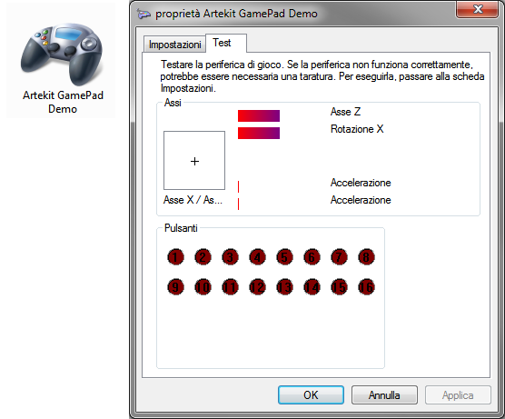
If everything went OK you will see the device in the Windows Control Panel, like in the following picture (the UI is in italian but you’ll get the idea).
Click here to download the source code.
The project is in KEIL uVision format. You can download the KEIL uVision evaluation version from www.keil.com.
That’s it. Have fun!



9 Responses
Nice! Just what I was looking for!
Hi ,
I just converted the Wii reading code for the stm429i Discovery board 🙂
This is working very well , thank you for showing us how to use it !!
Here it is :
https://sites.google.com/site/suprabotics/home/stm429-wii-classic-controller
Cheers.
Hi and thanks a lot for great tutorial. I have STM32F103RBT6. Can your code be exported easily to this chip? Or its a lot of work? I really can’t afford a new development board right now 🙁
Hi.
Yes, the project should compile and run as is.
Let us know if you find any problems.
Hi.
Really great turorial!
I use a custom made board based on STM32F103RBT6 and have a problem with USB.
—usb.c, usbInit()
while (pInfo->Current_Configuration == 0)
The program stucks on this condition.
What could be the problem?
Thank you.
Hi, Thank you.
It could be for many reasons. Mostly because the enumeration process is not completed.
If you are using the same code from this tutorial, check your connections and/or hardware.
Otherwise it could be wrong USB descriptors, USB interrupts not being processed, USB pins/clock/AF misconfigured, etc. Are you seeing any activity on the host side?
Hi,
I have a STM32 performance stick based on STM32F103RBT6 MCU. I am trying to use it as a USB HID keyboard.
I am also using USB mouse example as a base code.
I changed the descriptors accordingly for the HID keyboard and changed the Report descriptor.
I also wrote the report for sending the keycodes.
But the device is not getting recognized by the PC.
is there anything else I need to change for the PC to recognize it as a HID keyboard
Hi.
I wouldn’t know. If you are running a stable hardware and the same hardware works OK with other HID examples, there may be an error in the descriptors.
I’m sure there should be examples to simulate a keyboard out there.
Do you know how to add configuration options on the controller settings page? I want to add deadzone control, invert axis, combine axis, etc…