AK-USB-RS485-FD RS485 Line Drivers
Reference manual for the Artekit AK-USB-RS485-FD and AK-USB-RS485-FD-S boards.
Introduction
The RS485, also known as TIA-485(-A), EIA-485, supports serial communications using balanced mode (differential pair) and supports also multipoint systems. Can be used over long distances in electrically noisy environments.
The AK-USB-RS485-FD and AK-USB-RS485-FD-S are USB-to-RS485/422 converter boards that convert USB into RS485/422 signals and can be used to connect your PC/MAC/Raspberry Pi to a network of RS485/422 devices.
This guide covers both AK-USB-RS485-FD and AK-USB-RS485-FD-S boards, which are functionally and mechanically identical, except for the USB converter. The AK-USB-RS485-FD uses an FTDI chip and AK-USB-RS485-FD-S uses a SiLabs chip.

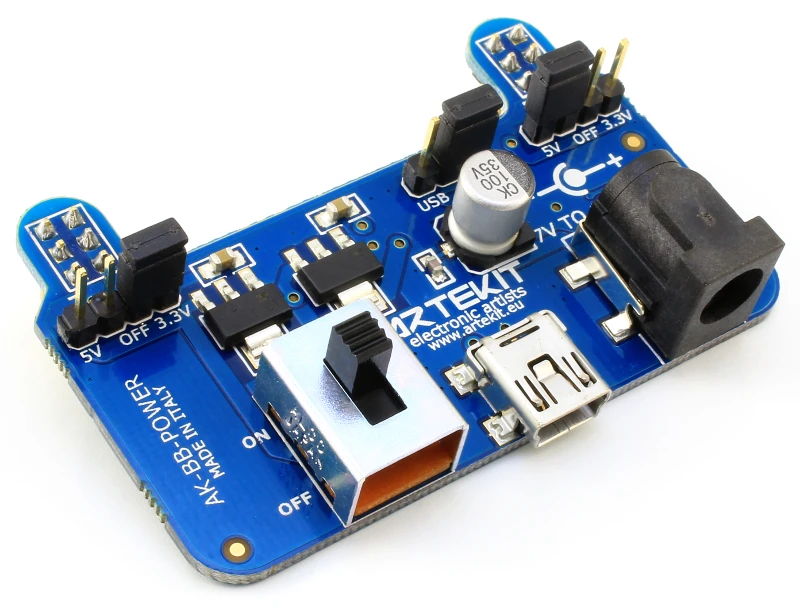
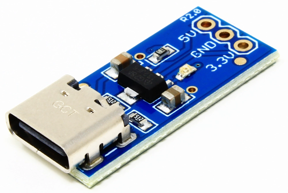
AK-USB-RS485-FD-S on the left and AK-USB-RS485-FD on the right.
Usually, a RS485/422 network is half-duplex, that is, a device in the network can either transmit or receive data. The AK-USB-RS485-FD communicates in full-duplex mode: it has two RS485/422 channels allowing to create a full-duplex, bidirectional communication link over a long distance. Being full-duplex, the communication link can be treated like a standard serial port as it does not require to check for collisions. This can be used, for example, to safely connect a PC and a Raspberry Pi over 1000m with a couple of wires and communicate as easily as if they were connected using a short RS232 cable.
Hardware overview
You can connect the board to your host device using a standard mini USB cable. The board is powered using the 5V from the USB cable so no external power supply is required.
The AK-USB-RS485-FD and AK-USB-RS485-FD-S can be purchased with soldered screw terminals that allows you to easily attach the wires to the board. You can choose to include the soldered screw terminals at the moment of purchase.

An AK-USB-RS485-FD board with and without screw terminals.
The board has two LEDs to indicate TX and RX activity. The yellow LED indicates RX (incoming data) activity, and the green LED indicates TX (outgoing data) activity.

Activity LEDs.
On the back of the board there are two solder jumpers to enable the on-board 120 Ohm load resistor in parallel with the network cables. You can enable the 120 Ohm resistors by dropping some solder to create a short circuit between the LOAD-AB pads for the RX side and LOAD-YZ pads for the TX side. This option must be enabled only on the first and the last devices in the network.

Solder jumpers for enabling load resistors.
Connecting to a network
The next picture shows how connect the AK-USB-RS485-FD or AK-USB-RS485-FD-S boards to a RS485/422 network. Note that the remote device you want to connect has to be full-duplex in order to be able to communicate with the board.

Typical connection between an AK-USB-RS485-FD and a remote device.
Connecting the board to the host
The AK-USB-RS485-FD and AK-USB-RS485-FD-S boards are seen by the host as an USB-to-Serial converter, and is accessed through a virtual serial port.
In order to use the board as a virtual serial port you might need to install some drivers. On modern operating systems (Linux, Windows 7 and up, OSX) the drivers should be already installed or will be downloaded automatically when you plug the board in for the first time.
In the case you still need to manually install the drivers, you can find them here:
- AK-USB-RS485-FD (FTDI): https://www.ftdichip.com/FTDrivers.htm
- AK-USB-RS485-FD-S (SiLabs): https://www.silabs.com/developers/usb-to-uart-bridge-vcp-drivers
For FTDI-based boards: there are two kind of drivers: VCP drivers for Virtual COM Port emulation. VPC is the most commonly used and the one that is automatically installed. D2XX drivers allow you to access the USB-to-Serial converter through a special library for advanced usage. We recommend the VCP drivers that will quickly allow you to use the board with programs like TeraTerm or PuTTY.
For both board versions, when the drivers are correctly installed, the host “sees” the board as a new COM port on Windows or ttyUSB on Linux.
Testing your setup
After you have installed the drivers you want to make sure that everything is working as it should with this simple loopback, local-echo test:
- Disconnect the board from the RS485/422 network.
- Connect A to Y and B to Z as in the picture here below.
- Connect the board to a USB host using a mini USB cable. A virtual serial port should be generated.
- Launch you preferred terminal program.
- Select the virtual serial port for the board.
- Disable the Local Echo in the terminal program (if any).
- Press any character key.
- Check if the transmitted character is read back in the terminal program. If the transmitted character is read back it means that your host, board and drivers are installed correctly and you are ready to join a RS485/422 network.

TX and RX channel loopback for testing
Additional resources
AK-USB-RS485-FD
AK-USB-RS485-FD-S


