The Artekit AK-RS232 family
User manual for the Artekit AK-RS232 family of boards.
Introduction
The Artekit AK-RS232 family of board converts TTL voltage levels into RS232 levels, allowing you to connect any TTL/UART device to RS232-compatible devices. Useful when you want to connect your MCU/Arduino/Raspberry PI to a PC serial port.
In this guide we will learn about the different models of the AK-RS232 family and how to use them.
Suggested reading: The EIA RS-232 article from Wikipedia
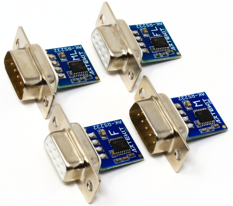
The Artekit AK-RS232 family of boards.
Models
Basically, the AK-RS232 family is composed of two models:
- the standard AK-RS232 board
- and the AK-RS232-LED board
Both models operate identically and have the same size and connections. The only difference between the two is that the AK-RS232-LED mounts four LEDs that reflect the state of the four communication signals and allow you to easily see the state of the data flow.
The boards also host a standard male or female DB9 connector and all the models perfectly fit into the standard DB9 plastic housing. You can choose the gender of the connector and whether to include the DB9 plastic housing at the moment of purchase.
| MODEL | CONNECTOR GENDER | LEDs |
|---|---|---|
| AK-RS232 (male connector) | MALE | NO |
| AK-RS232 (female connector) | FEMALE | NO |
| AK-RS232-LED (male connector) | MALE | YES |
| AK-RS232-LED (female connector) | FEMALE | YES |
Characteristics for the entire family
- Converts signals from TTL to RS232 and from RS232 to TTL.
- High speed (typically 400 kbps, 300 kbps minimum guaranteed).
- Works with any PC or Laptop.
- Suitable to interface any microcontroller, such as Microchip PIC, Atmel and any Cortex.
Learn more about the TTL/RS232 signals conversion by reading:
The AK-3232 usage guide, and Why do I need a RS232 Level Converter?
Hardware description
Since all the models of the family have the same layout/size/pinout, and the only differences would be about the DB9 connector and/or LEDs, we’ll describe the hardware using a AK-RS232 with a female DB9 connector.
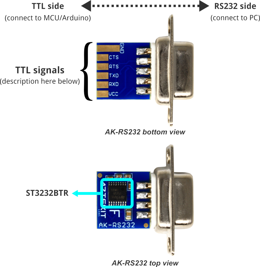
Artekit AK-RS232 with female connector.
Pinout
The following table describes the pads of the AK-RS232 TTL side (first column), where in your TTL device (MCU, Arduino, etc.) this pad should be connected (second column), and also the corresponding pin on the DB9 connector, male and female (third and fourth columns).
| PAD | CONNECTED TO | PIN ON MALE DB9 CONNECTOR | PIN ON FEMALE DB9 CONNECTOR |
|---|---|---|---|
| GND | TTL Ground | 5 (Ground) | 5 (Ground) |
| CTS | TTL CTS | 8 (Input, Clear To Send) | 7 (Input (Clear To Send) |
| RTS | TTL RTS | 7 (Output, Request To Send) | 8 (Output, Request To Send) |
| TXD | TTL TX | 3 (Output, Transmit Data) | 2 (Output, Transmit Data) |
| RXD | TTL RX | 2 Input, Receive Data) | 3 (Input, Receive Data) |
NOTE: RI (Ring Indicator), CD (Carrier Detect), DSR (Data Set Ready) and DTR (Data Terminal Ready) RS232 signals are not connected and thus not available.
Power supply
The board accepts 3V to 5V as the power supply. The TTL signal levels must match the power supply. That is, if you are powering the board with 3.3V then every signal on the TTL side must be 0V (when negative) and 3.3V (when positive).
Details
The boards are built around an STmicroelectronics ST3232BTR IC. This IC is in charge of doing all the TTL-to-RS232 level translation. It has two TX channels and two RX channels that we use to connect the TXD/RTS and RX/CTS pairs between the TTL side and the RS232 side.
The AK-RS232-LED boards also contain four LEDs connected as the following table:
| COLOR | SIGNAL |
|---|---|
| GREEN | RXD |
| RED | TXD |
| WHITE | RTS |
| BLUE | CTS |
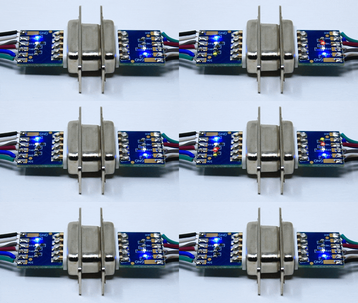
AK-RS232-LED board LEDs.
Connecting the board
The connection is very simple. The TTL pads are named using the DTE (Computer side) point-of-view:
- TXD and RTS signals are inputs
- and RXD and CTS are outputs.
See the following picture. On the left side there is your TTL device, that is, your MCU/Arduino, and the respective connections. The arrows denote the signals direction.

AK-RS232 and AK-RS232-LED connections.
All AK-RS232 family boards have the same pinout and connection scheme. Note that the DB9 connector chassis is not connected to GND, and remains floating.
Board dimensions
All AK-RS232 family boards have the same dimensions.
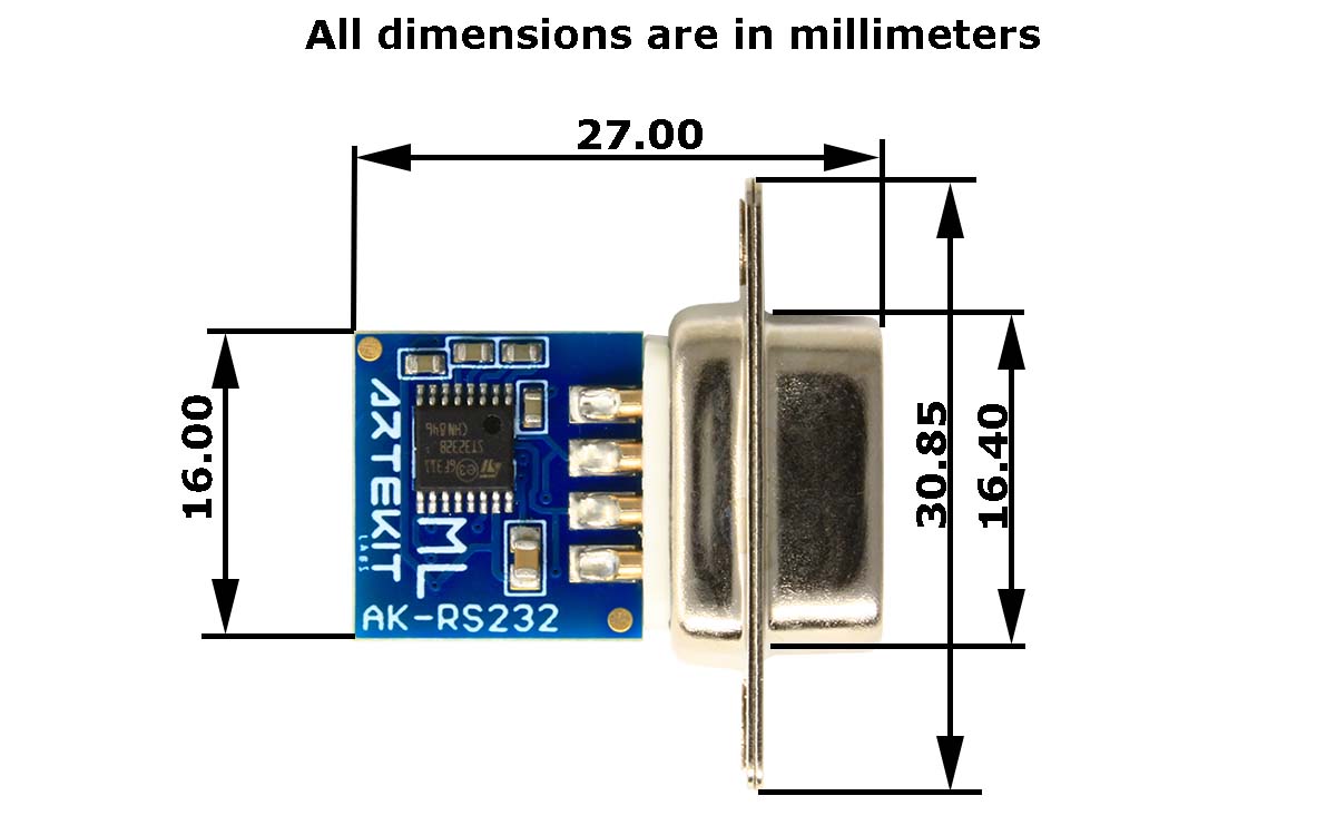
Board dimensions.
DB9 housing
Optionally, a DB9 plastic case with all the bolts and screws can be purchased together with an AK-RS232 board. The board fits nicely into the case even when all the connection pads are used.
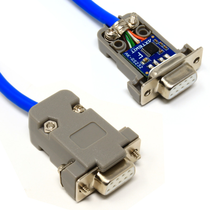
AK-RS232 with plastic case.
Additional resources
- Artekit AK-RS232 product page
- Artekit AK-RS232-LED product page
- ST3232BTR datasheet
- Schematics for the Artekit AK-RS232 (female connector)
- Schematics for the Artekit AK-RS232 (male connector)
- Schematics for the Artekit AK-RS232-LED (female connector)
- Schematics for the Artekit AK-RS232-LED (male connector)

