Artekit AK-DS2482S-100 breakout
Reference manual for the Artekit AK-DS2482S-100 breakout board.
Introduction
The AK-DS2482S-100 breakout board is an I²C to 1-Wire bridge featuring bidirectional protocol conversion, based on the Maxim DS2482S-100 IC. It enables easy interfacing with a wide range of 1-Wire devices—such as EEPROMs, sensors, and iButtons (formerly Dallas Buttons) from Maxim Integrated.

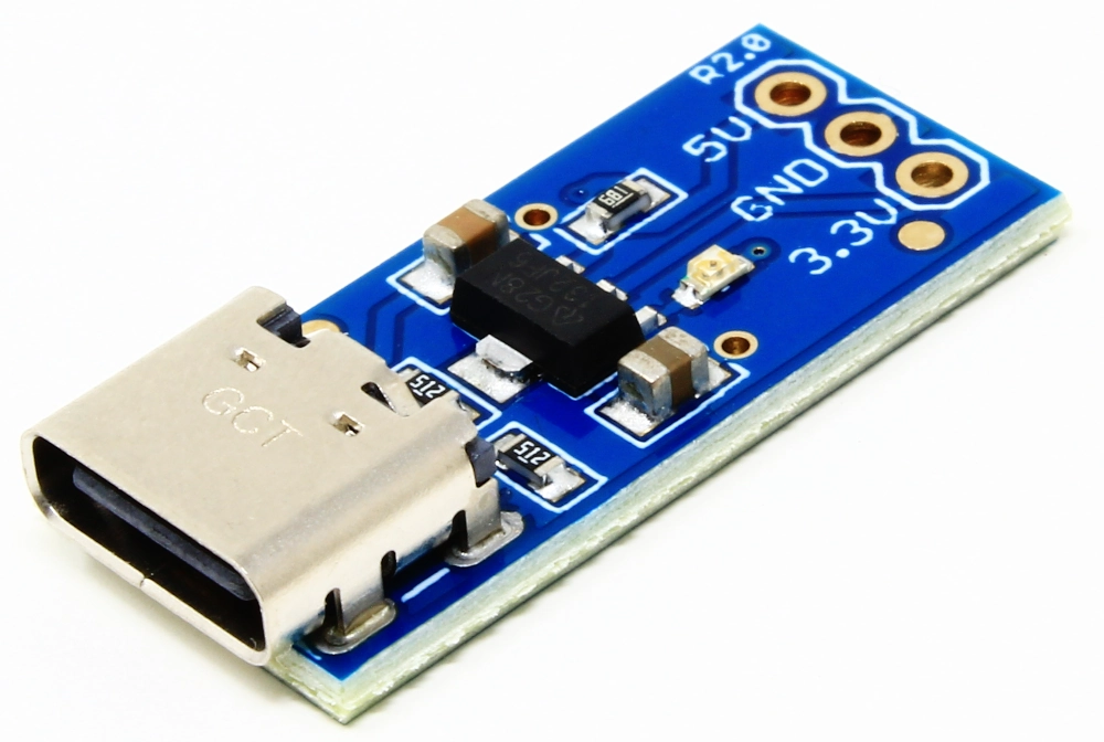
An Artekit AK-DS2482S-100 breakout board.
Communicating with 1-Wire devices typically requires precise, time-critical signal generation, which makes software implementations either resource-intensive or unreliable on non-real-time operating systems.
The AK-DS2482S-100 board simplifies this process by offloading the timing-sensitive tasks to the hardware. It allows you to control one or more 1-Wire slave devices—like temperature sensors or memory chips—using straightforward I²C commands. The board handles the full protocol conversion between an I²C master (e.g., a microcontroller) and the connected 1-Wire devices.
It supports I²C bus speeds of 100kHz and 400kHz, operates from 2.9V to 5.5V, and includes onboard solder jumpers to enable I²C pull-up resistors. A dedicated jumper also enables the Strong Pull-Up (SPU) feature via the onboard MOSFET, useful for powering high-demand 1-Wire devices during data transfer.
Features
- I²C to 1-Wire bridge
- Wide power supply range: 2.9V to 5.5V
- Supports 100kHz and 400kHz I²C bus speeds
- –40 °C to +85 °C operating temperature range
- Onboard MOSFET for Strong Pull-Up control via PCTLZ pin
- 1-Wire master I/O with selectable active or passive pull-up
- Supports reset/presence detect, 8-bit, single-bit, and 3-bit 1-Wire I/O sequences
- Standard and overdrive 1-Wire communication speeds
- Compatible with EEPROMs, temperature sensors, and other 1-Wire devices with momentary high current requirements
- Strong 1-Wire pull-up via internal low-impedance signal path
- Two mounting holes for secure installation
- ENIG (Electroless Nickel Immersion Gold) plated contacts
- Compact PCB footprint
Electrical Characteristics
Supply Voltage: 2.9 V to 5.5 V. Ensure your 1-Wire peripherals also support the chosen voltage.
I²C Voltage Levels: Follows VCC. If your microcontroller is 3.3 V, supply the board at 3.3 V. If 5 V logic, you can supply at 5 V.
I²C Pull-Ups: Onboard selectable 47K pull-ups for SDA and SCL. Use them if your system does not already include pull-ups.
1-Wire Pull-Up: A weak pull-up is always present; a strong pull-up can be enabled by the SPU jumper and software commands for high-current events.
I²C Address: Default address is
0x18(if A0 and A1 are both low). You can alter the address by tying A0 or A1 high/low as per the DS2482S-100 datasheet.SPU MOSFET: An Onsemi/Fairchild BSS84 P-Channel MOSFET is used on the breakout to provide the Strong Pull-Up (SPU) required by certain 1-Wire devices. The DS2482S-100 controls this MOSFET via its PCTLZ pin; when software enables the SPU feature, the BSS84 is switched on, delivering a higher current to the 1-Wire line. This extra current is essential for operations like EEPROM writes or temperature conversions when using parasite-powered 1-Wire devices.
Hardware overview

| Pin name | Pin mode | Description |
|---|---|---|
| VCC | Power | 2.9V to 5.5V DC voltage |
| SCL | Output | I²C bus clock |
| SDA | Input/Output | I²C bus data |
| A0 | Input | Address select 0 (onboard 47K pull-down resistor) |
| A1 | Input | Address select 1 (onboard 47K pull-down resistor) |
| 1-Wire | Input/Output | 1-Wire data bus |
| GND | Power | Common ground |
Optional solder jumpers
- I2C PU (Pull-Up solder jumpers): join these pads to enable onboard pull-ups for SCL and SDA if needed.
- SPU (Strong Pull-Up solder jumper): join these pads to enable the onboard MOSFET that supplies extra current to the 1-Wire bus (e.g., for parasite-powered devices).
Usage
- Power and Ground
- Connect VCC to 3.3 V or 5 V (within the 2.9–5.5 V range).
- Tie GND to your system ground.
- Connect VCC to 3.3 V or 5 V (within the 2.9–5.5 V range).
- I²C Lines
- Connect SCL and SDA to the corresponding pins on your microcontroller.
- Check whether you need the onboard pull-ups (I2C PU solder jumpers).
- Connect SCL and SDA to the corresponding pins on your microcontroller.
- 1-Wire Connection
- Hook the 1-WIRE pin to any 1-Wire slave devices.
- If your devices use parasite power, enable the SPU jumper and configure your software to activate the strong pull-up at appropriate times.
- Hook the 1-WIRE pin to any 1-Wire slave devices.
- Address Pins
- A0 and A1 can be used to modify the DS2482S-100 I²C address if multiple AK-DS2482S-100 boards share the same I²C bus.
- Software Integration
- In your code, open an I²C channel at 100 kHz or 400 kHz and address the DS2482S-100 at
0x18(or the modified address). - Send DS2482 commands (reset 1-Wire bus, read/write bytes, etc.) to manage 1-Wire slave devices.
- In your code, open an I²C channel at 100 kHz or 400 kHz and address the DS2482S-100 at
Example of board connection
Below is a simple exampling demonstrating the connections between the AK-DS2482S-100 with an Arduino Uno. Adjust pins and voltage if using another microcontroller.

An Artekit AK-DS2482S-100 board connected to an Arduino UNO.
| AK-DS2482S-100 | Arduino Uno | Notes |
|---|---|---|
| VCC | 5V | Supply the breakout board at 5V. |
| GND | GND | Common ground |
| SCL | A5 (SCL) | I²C clock line on the Arduino Uno. |
| SDA | A4 (SDA) | I²C data line on the Arduino Uno. |
NOTE: The 1-Wire devices should be connected to the 1-WIRE pin of the AK-DS2482S-100 board. Connect the 1-Wire devices to the common ground as shown in the picture above. If using parasite power, enable SPU on the board and in software.
Board dimensions