Artekit AK-BTS716G
User manual for the Artekit AK-BTS716G, a board with four optically-isolated, solid-state relay outputs.
Introduction
The Artekit AK-BTS716G is a board with four optically-isolated outputs capable of providing power to high-voltage devices like lamps, heaters, motors or any resistive or capacitive load, delivering up to 40V @ 1A on every output. It’s the ideal board to power on and off high DC voltage devices from a low-voltage circuit like an Arduino or Raspberry Pi.
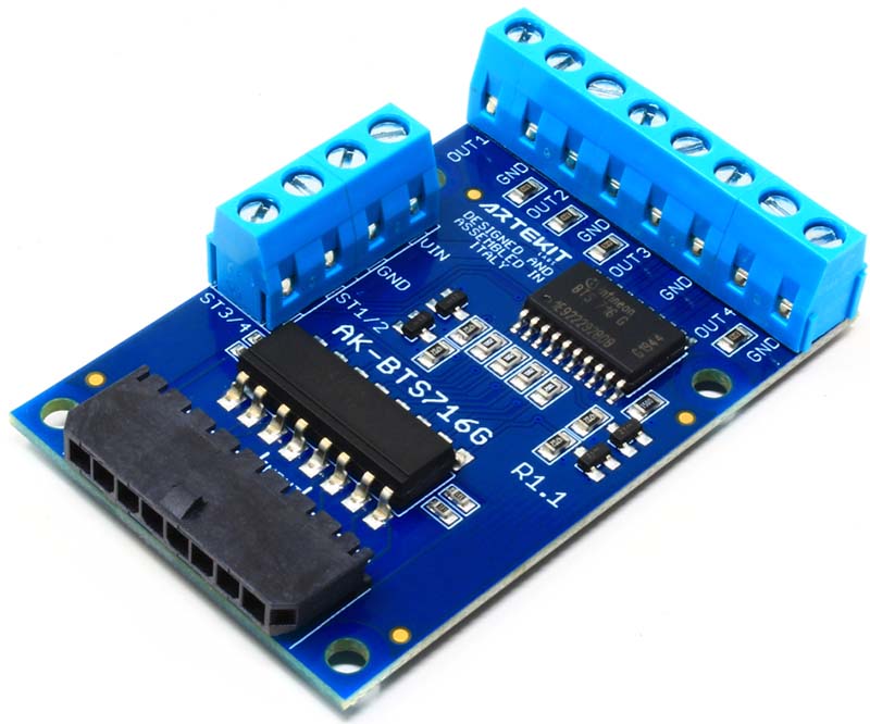
Artekit Labs AK-BTS716G board.
From one side of the board you will provide a high-voltage source (from 5.5V up to 40V). This voltage will be delivered to the outputs through a solid-state relay. Each relay channel is activated with a corresponding input pin on the other side of the board. The input pins (and thus your low-voltage circuit) is protected with opto-isolators, providing protection up to 5KV.
The AK-BTS716G supports several types of inductive and resistive loads, like DC motors, electro-valves, solenoids, fluid pumps, heathers and lamps.
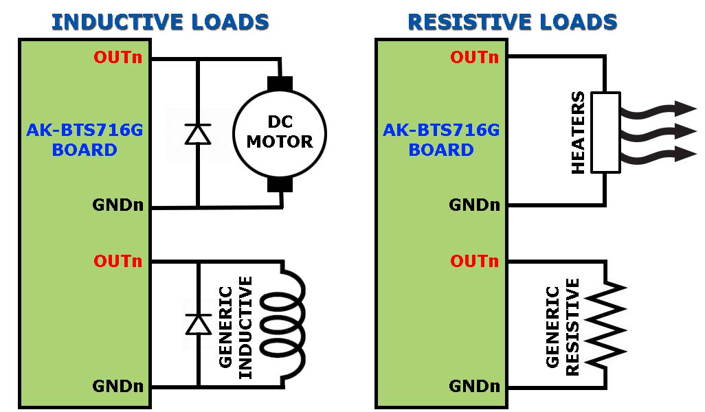
Artekit Labs AK-BTS716G - supported load types.
If you choose inductive types, remember to add an appropriate diode (for example, a 1N4002) in parallel with the load to avoid the reverse pulse when the load changes state.
All the above is packed in a little board, with convenient screw terminal blocks for the high-voltage input and the four outputs. For the low-voltage connections you can choose to either use an industrial Molex connector (sold separately) or regular 0.1” (2.54mm) header pins.
Hardware overview
The main component of the AK-BTS716G board is the Infineon BTS716G, with four high-side, solid-state relays capable of outputting up to 40V @ 1A, with an internal resistance of 140mΩ.
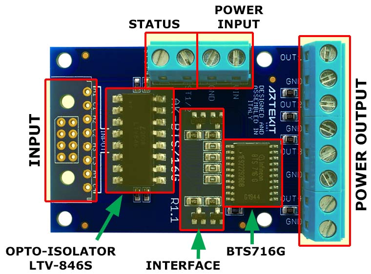
Artekit Labs AK-BTS716G board - hardware overview.
Between the solid-state relays and the inputs there is the LTV-846S opto-isolator, protecting your low-voltage circuit from noise or spikes resulting from toggling high-voltage devices like DC motors with the outputs. Each one of the opto-isolator input has a 330Ω resistance connected in series.
NOTE: For concepts like solid-state relay, opto-isolation and high-side/low-side there is a little addendum at the end of this guide with explanations.
You will connect your high-voltage devices on the screw terminal blocks on the right (POWER OUTPUT in the above picture). On the screw terminals labeled POWER INPUT you will connect a power supply from 5.5V to 40V (depending on the voltage your devices require).
In the connector labeled INPUT in the above picture you will find the anodes and cathodes of the opto-isolator. Here you can solder an industrial Molex connector or standard single or dual row, straight or right angle, 0.1” (2.54mm) headers.
Here follows a description of every input/output of the board:
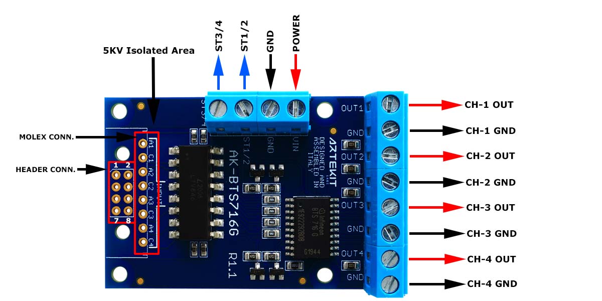
Artekit Labs AK-BTS716G board - inputs and outputs
| NAME | TYPE | DESCRIPTION |
|---|---|---|
| ST1/2 | OUT | Status channel 1 and 2. Open Drain. 0 = channel 1 or 2 failure |
| ST3/4 | OUT | Status channel 3 and 4. Open Drain. 0 = channel 3 or 4 failure |
| GND | PWR | Input ground |
| POWER | PWR | Power input. 5.5V to 40 VDC |
| OUT1 | PWR | Channel 1 output |
| OUT2 | PWR | Channel 2 output |
| OUT3 | PWR | Channel 3 output |
| OUT4 | PWR | Channel 4 output |
NOTE: All output grounds (labeled as GND in the board) are common, and are internally connected.
Inputs for the Molex microfit industrial connector:
| NAME | TYPE | DESCRIPTION |
|---|---|---|
| A1 | IN | Opto-isolator LED anode (channel 1) |
| C1 | IN | Opto-isolator LED cathode (channel 1) |
| A2 | IN | Opto-isolator LED anode (channel 2) |
| C2 | IN | Opto-isolator LED cathode (channel 2) |
| A3 | IN | Opto-isolator LED anode (channel 3) |
| C3 | IN | Opto-isolator LED cathode (channel 3) |
| A4 | IN | Opto-isolator LED anode (channel 4) |
| C5 | IN | Opto-isolator LED cathode (channel 4) |
Inputs for the 0.1” (2.54mm) headers pins:
| PIN | TYPE | DESCRIPTION |
|---|---|---|
| 1 | IN | Opto-isolator LED anode (channel 1) |
| 2 | IN | Opto-isolator LED cathode (channel 1) |
| 3 | IN | Opto-isolator LED anode (channel 2) |
| 4 | IN | Opto-isolator LED cathode (channel 2) |
| 5 | IN | Opto-isolator LED anode (channel 3) |
| 6 | IN | Opto-isolator LED cathode (channel 3) |
| 7 | IN | Opto-isolator LED anode (channel 4) |
| 8 | IN | Opto-isolator LED cathode (channel 4) |
Connectors
The AK-BTS716G comes with the screw terminals already soldered in (power and outputs connectors). For the input connector there are two options to choose from when purchasing the board:
- You can include a Molex microfit connector (that comes unsoldered) with both male and female counterparts, and the pins, ready to be crimped.
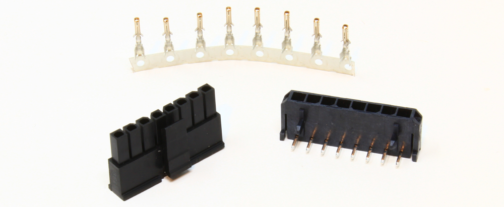
The Molex microfit connector.
- Or you can purchase the board without the Molex connector and solder standard 0.1” (2.54mm) header strips.
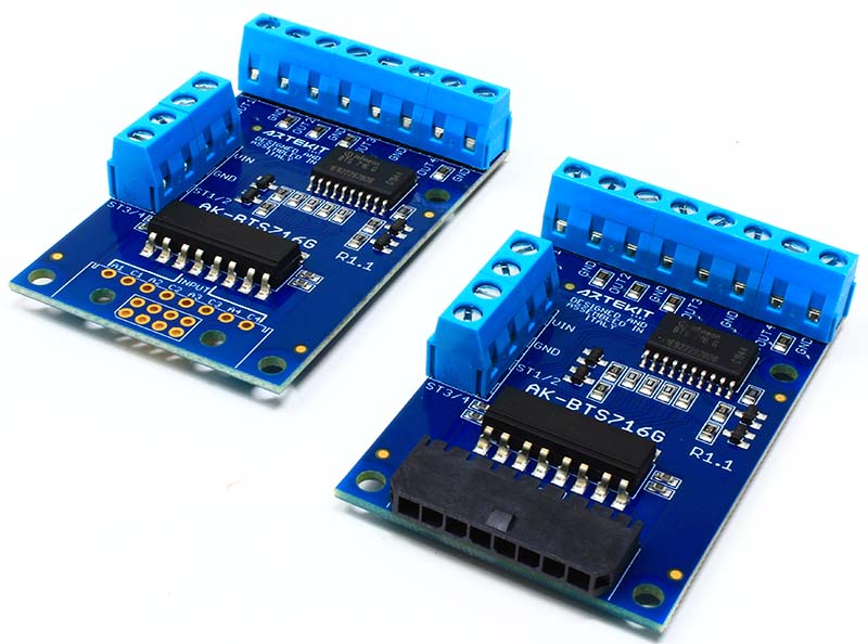
Artekit Labs AK-BTS716G board with and without the Molex connector
Connecting the board
To use the board:
Connect a power supply (from 5.5V up to 40V, accordingly with the voltage your device needs) in the POWER and GND screw terminals.
On the outputs of the board you will connect the high-voltage device ground and VCC.
Connect your low-voltage circuit to the inputs of the board. A low-voltage device could be an Arduino or Raspberry Pi, or a simple switch. The inputs are connected directly to internal LEDs of the opto-isolator. Turning an LED on/off will enable/disable a relay output. Refer to the following picture:
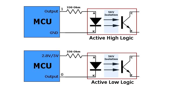
Opto-isolator LEDs connections.
As you can see in the above picture, you can turn on and off an opto-isolator LED by either toggling the voltage to the LED anode while connecting the cathode to ground, or by providing a fixed voltage to the LED anode and toggling a voltage to the cathode.
The 330 Ohm resistor shown here above is already soldered in the board.
NOTE: Each LED in the opto-isolator is independent from the other LEDs, and can be driven by different MCUs, if required.
Getting more output current
The AK-BTS716G board can manage up to 4A (1A per channel). To get more current you can put 2 o more channels in parallel. It is important to set the inputs in parallel too (so they are enabled/disabled at the same time).
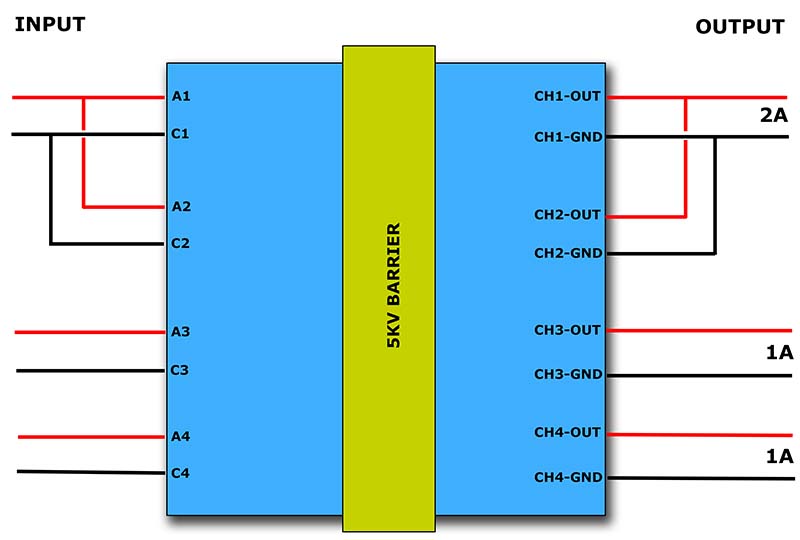
Connects the outputs in parallel to get more output current.
Arduino Connection
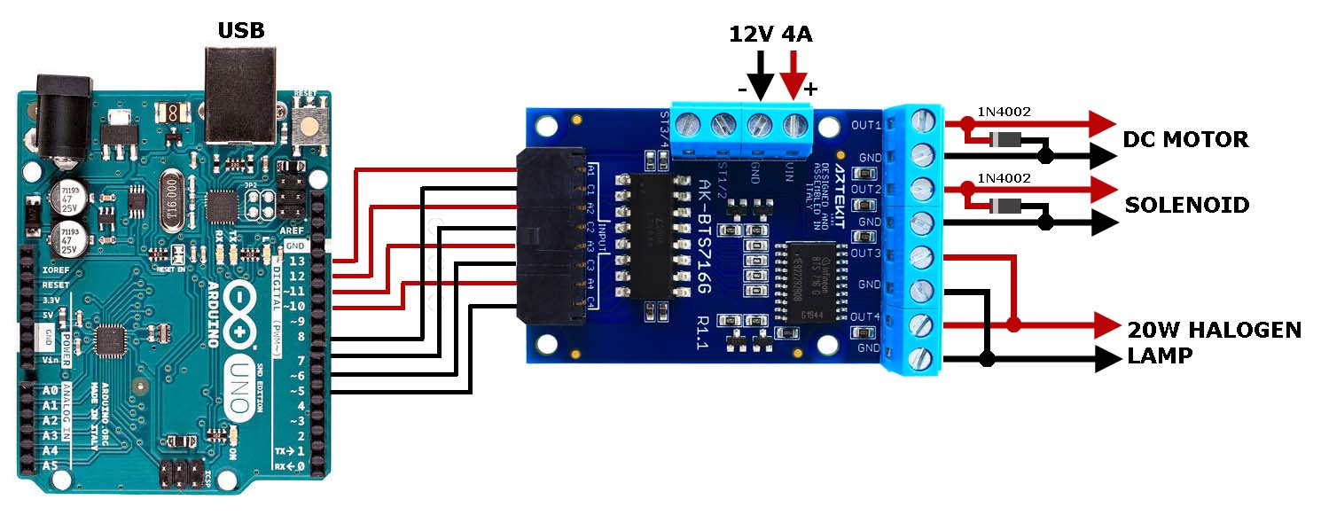
We have prepared a little demo connecting the AK-BTS716G to the popular Arduino UNO board. In this demo we have the Arduino UNO driving a DC motor, a solenoid and a lamp through the AK-BTS716G.
These are the connections between the AK-BTS716G and the Arduino UNO:
| ARDUINO PIN | AK-BTS716G PIN | DESCRIPTION |
|---|---|---|
| 10 | A4 | 20W Halogen Lamp |
| 11 | A3 | 20W Halogen Lamp |
| 12 | A2 | 1A Open Doors Solenoid |
| 13 | A1 | 1A DC Motor |
| GND | C1 | Led Cathode 1 |
| GND | C2 | Led Cathode 2 |
| GND | C3 | Led Cathode 3 |
| GND | C4 | Led Cathode 4 |
The halogen lamp used here drains ~20W (about 1.7A) so due to its high current consumption we have used two AK-BTS716G channels (CH 3 and CH4). To simplify the wiring we have connected the AK-BTS716G pins A3 and A4 to pins 11 and 10 respectively on the Arduino UNO board, but the sketch activates or deactivates both pins at the same time. In this way it is as if they were electrically connected together.
Here is the code needed to run the demo. Copy-paste it into the Arduino IDE.
#define PIN_MOTOR       13
#define PIN_SOLENOID    12
#define PIN_LAMP1       11
#define PIN_LAMP2       10
#define PIN_C1          8
#define PIN_C2          7
#define PIN_C3          6
#define PIN_C4          5

#define MOTOR_ON        2
#define MOTOR_OFF       2
#define SOLENOID_ON     1
#define SOLENOID_OFF    1
#define LAMP_ON         2
#define LAMP_OFF        2

//  Global timing variables in seconds

int MotorOn = 2;
int MotorOff = 2;
int MotorSwap = 0;
int SolenoidOn = 1;
int SolenoidOff = 1;
int SolenoidSwap = 0;
int LampOn = 3;
int LampOff = 3;
int LampSwap = 0;

void setup()
{
    pinMode(PIN_MOTOR,OUTPUT);
    pinMode(PIN_SOLENOID,OUTPUT);
    pinMode(PIN_LAMP1,OUTPUT);
    pinMode(PIN_LAMP2,OUTPUT);

    // We'll use pins 8, 7, 6 and 5 as GND return for the LEDs

    pinMode(PIN_C1,OUTPUT);
    pinMode(PIN_C2,OUTPUT);
    pinMode(PIN_C3,OUTPUT);
    pinMode(PIN_C4,OUTPUT);

    // All LEDs cathodes to GND

    digitalWrite(PIN_C1,LOW);
    digitalWrite(PIN_C2,LOW);
    digitalWrite(PIN_C3,LOW);
    digitalWrite(PIN_C4,LOW);

    // Initializing all LEDs to OFF

    digitalWrite(PIN_MOTOR,LOW);
    digitalWrite(PIN_SOLENOID,LOW);
    digitalWrite(PIN_LAMP1,LOW);
    digitalWrite(PIN_LAMP2,LOW);

    // Debug

    Serial.begin(9600);
    Serial.println("Serial OK");
}

void loop()
{
    // Motor

    if (MotorSwap == 0)
    {
        digitalWrite(PIN_MOTOR,HIGH);
        if (--MotorOn == 0)
        {
            MotorSwap = 1;
            MotorOn = MOTOR_ON;
            Serial.println("MOTOR ON");
        }
    } else {
        digitalWrite(PIN_MOTOR,LOW);
        if (--MotorOff == 0)
        {
            MotorSwap = 0;
            MotorOff = MOTOR_OFF;
            Serial.println("MOTOR OFF");
        }
    }

    // Solenoid

    if (SolenoidSwap == 0)
    {
        digitalWrite(PIN_SOLENOID,HIGH);
        if (--SolenoidOn == 0)
        {}
            SolenoidSwap = 1;
            SolenoidOn = SOLENOID_ON;
            Serial.println("SOLENOID ON");
        }
    } else {
        digitalWrite(PIN_SOLENOID,LOW);
        if (--SolenoidOff == 0)
        {
            SolenoidSwap = 0;
            SolenoidOff = SOLENOID_OFF;
            Serial.println("SOLENOID OFF");
        }
    }

    // Lamp

    if (LampSwap == 0)
    {
        digitalWrite(PIN_LAMP1,HIGH);
        digitalWrite(PIN_LAMP2,HIGH);
        if (--LampOn == 0)
        {
            LampSwap = 1;
            LampOn = LAMP_ON;
            Serial.println("LAMP ON");
        }
    } else {
        digitalWrite(PIN_LAMP1,LOW);
        digitalWrite(PIN_LAMP2,LOW);
        if (--LampOff == 0)
        {
            LampSwap = 0;
            LampOff = LAMP_OFF;
            Serial.println("LAMP OFF");
        }
    }

    delay(1000);
}
A little bit of theory
What is a solid-state relay?
A solid-state relay works in a similar way to a mechanical relay where the physical contact is replaced by a high current MOSFET, maintaining the functionality and adding some advantages. The mechanical relay has physical contacts that often produce little sparks when changing state, and this cause oxidations increasing the contact resistance. Also they get dirty and can cause random defects over time. Solid-state relays also have the advantage of its small size and its long duration.
High Side ? Low Side?
There are two types of solid-state relays (and switches in general): they can be either high-side or low-Side. High-side types, as in the AK-BTS716G case, controls the current flow like a on/off switch between the power supply and the load. In the low-Side type, the switch sits between the load and ground.
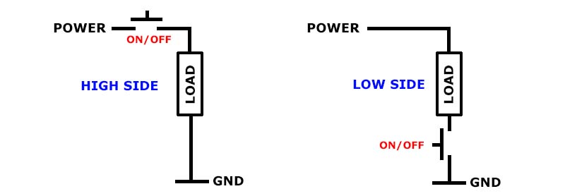
High-side and low-side relay/switch.
About opto-isolators
A typical opto-isolator (also known as photocouplers) consists in an LED and a phototransistor. When the LED turns on, the phototransistor receives its light and operates on a circuit just like a common transistor.
Opto-isolators are typically used to, well, isolate a part of your circuit from another one. The only thing that these two circuits share (in the case of the AK-BTS716G) is light, avoiding electrical noise from high-voltage devices to reach the low-voltage circuit.
In the AK-BTS716G board the opto-isolation is achieved by the LTV-846S device, containing 4 pairs of LEDs/phototransistors in a single package and providing up to 5KV of protection.
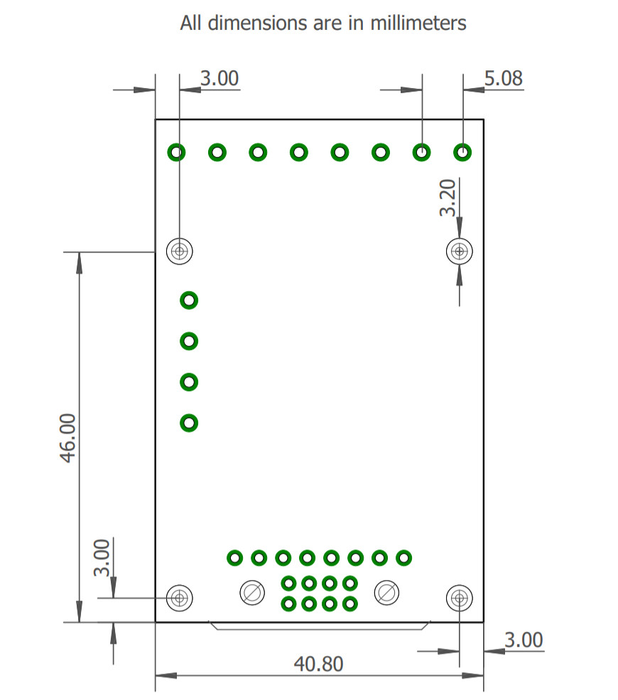
Board dimensions
