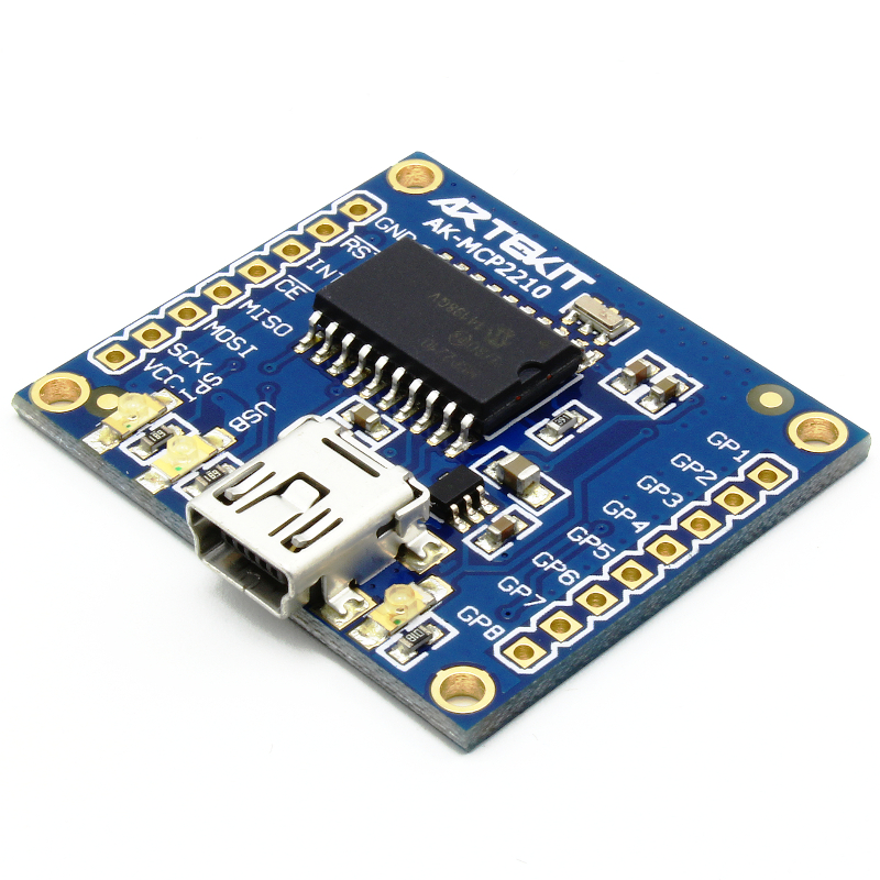
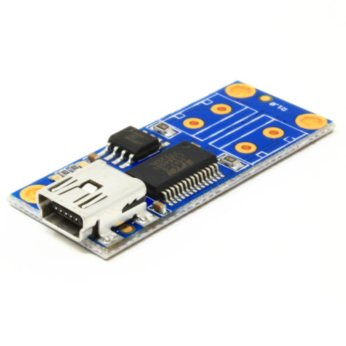
This board allows you to communicate with a SPI slave device through USB. The MCP2210 acts as a bridge between a SPI slave device and your PC/MAC. The MCP2210 is seen as a HID device, so there is no need to install a driver.
On the board there are also 8 general purpose input/output pins that you can drive from USB. These pins can also have a dedicated function, like Chip Select, or blinking a LED when there is ongoing SPI communication or when the USB is connected. We have added LEDs on the board that you can select by a solder jumper on the back of the board (a LED connected to GPIO3 for SPI communication and a LED on GPIO5 for USB).
The MCP2210 is highly configurable: you can choose SPI modes, transmission delays, bit rates, chip select assignment on any GPIO (this is nice for connecting several SPI slaves on the SPI bus). You can even configure it with your own USB VID and PID. All these parameters can be saved on the embedded EEPROM for the next start-up.
The board works with a power supply from 3.3V up to 5V. You can choose the operating voltage with a solder jumper on the back of the board. When 3.3V is selected, the on-board LDO regulator jumps in and converts the 5V supply from the USB into 3.3V.
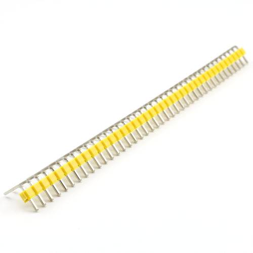
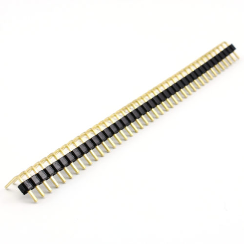
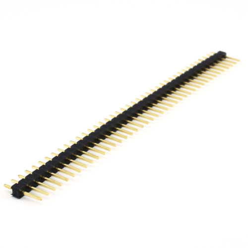
The board as usual includes four mounting holes and 0.1″ (2.54mm) spaced pins.
On the links here below you can find libraries and utilities from the Microchip MCP2210 page. Also, there are links to libraries for Linux hosted on GitHub and provided by the community.
Features
- Input from 3.3V up to 5V
- On-board LDO regulator
- Full-speed HID USB (12 Mb/s)
- Fully configurable
- No need of USB drivers
- SPI bit rates from 1500 bps up to 12 Mbps
- SPI transactions lengths of up to 65535 bytes long
- Mounting holes.
Documents
Hardware
Links



Comments
You must be logged in to post a comment.